English
English
Español
Português
русский
français
日本語
Deutsch
Tiếng Việt
Italiano
Nederlands
ไทย
Polski
한국어
Svenska
magyar
Malay
বাংলা
Dansk
Suomi
हिन्दी
Pilipino
Türk
Gaeilge
عربى
Indonesia
norsk
اردو
čeština
Ελληνικά
Українська
Javanese
فارسی
தமிழ்
తెలుగు
नेपाली
Burmese
български
ລາວ
Latine
Қазақ
Euskal
Azərbaycan
slovenský
Македонски
Lietuvos
Eesti Keel
Română
Slovenski
मराठी
Српски
Esperanto
Afrikaans
Català
עִברִית
Cymraeg
Galego
Latvietis
icelandic
יידיש
Беларус
Hrvatski
Kreyòl ayisyen
Shqiptar
Malti
lugha ya Kiswahili
አማርኛ
Bosanski
Frysk
ជនជាតិខ្មែរ
ქართული
ગુજરાતી
Hausa
Кыргыз тили
ಕನ್ನಡ
Corsa
Kurdî
മലയാളം
Maori
Монгол хэл
Hmong
IsiXhosa
Zulu
Punjabi
پښتو
Chichewa
Samoa
Sesotho
සිංහල
Gàidhlig
Cebuano
Somali
Точик
O'zbek
Hawaiian
سنڌي
Shinra
հայերեն
Igbo
Sundanese
Lëtzebuergesch
Malagasy
Yoruba
Javanese
Banbala
Pokjoper
Divih
Philippine
Gwadani
Elokano

While series‑constant‑power heating cables deliver outstanding performance for ultra‑long pipeline thermal maintenance, overall system reliability heavily depends on cable layer‑by‑layer construction quality and correct power‑end termination work. Poor handling at power‑input junctions frequently leads to premature system failures in field‑deployed trace‑heating projects.
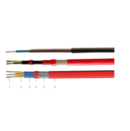
HGC‑1 and HGC‑3 adopt a well‑defined multi‑layer structure: resistive heating element, heating‑element insulating barrier, inner protective sheath, metallic braided shielding layer and outer insulating jacket. The metal braid serves dual purposes: mechanical shielding and protective earthing. Where cables face chemical splash, corrosive soil or underground burial conditions, project specifiers can select the optional fluoroplastic outer sleeve fitted outside the braid layer to add extra chemical‑attack resistance.
Manufacturer technical guidance highlights cold‑end connection as the preferred power‑entry method to maximize series‑cable service lifetime. Field procedures require stripping back outer and inner sheaths as well as core insulation to expose resistive heating conductors. Heating cores and pre‑stripped cold‑transition wires are mechanically crimped by copper connectors. Joint sections are wrapped with insulating tape, while metal braid must remain exposed for protective earthing. Four‑layer heat‑shrink sleeves are then fitted sequentially and thermally shrunk to seal the joint region tightly. This standardized workflow mitigates risks of moisture ingress, short‑circuit and mechanical damage at power‑connection points.
With broad voltage‑rating coverage, wide operating‑temperature window and hazardous‑area suitability, HGC‑1 / HGC‑3 underline that high‑performance industrial heat‑tracing solutions rely equally on core heating‑element technology, high‑grade layered materials and complete field‑installation procedural specifications for global industrial end‑users.